16+
Years of Experience*
100+
Projects Completed*
10+
Countries Served*
75%
Business Growth*

* Figures represent documented company operational metrics subject to final client confirmation prior to publication.

Mechanical assembly modeled in 3D CAD Mechanical engineering drawings and detailing
HYDERABAD Design Center · India

Engineering support for manufacturers who need it right the first time

Mterqubee is a mechanical engineering and design company based in Hyderabad, India. We help manufacturers, equipment builders, and product developers design, analyze, detail, and automate mechanical machinery and parts.

Our multidisciplinary team of mechanical design engineers, stress analysts, and manufacturing support specialists integrates directly into your workflow. We take care of the detailed CAD modeling, tolerance stack-ups, drafting, and design automation so your internal engineers can focus on core innovation and commercial milestones.

Design 3D parametric CAD models & assembly drawings
Analyse Finite element stress & thermal simulation
Prototype Concept verification & functional prototyping
Automate DriveWorks configurators & automated 2D outputs

Complete Engineering Services

Eleven core capabilities aligned with your project scope, from mechanical design and simulation to electronics, component engineering, and technical documentation.

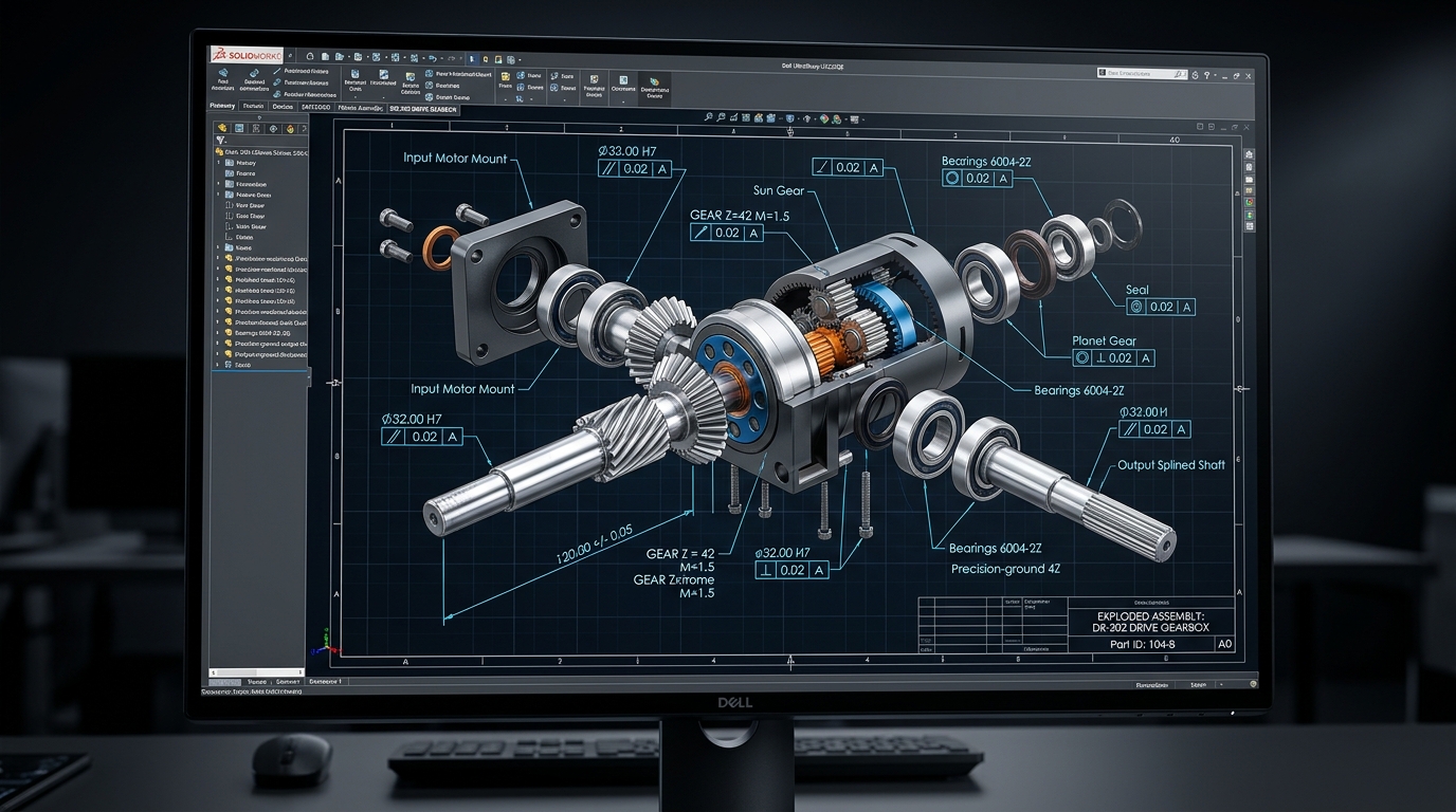
3D CAD modeling component on engineering screen 01
.SLDPRT .SLDASM .STEP AP242

3D CAD Modeling

Parametric solid and surface modeling for mechanical parts and large multi-component assemblies. Built with clear parent-child feature trees for seamless downstream updates.

  • CAD software master models & top-down assemblies
  • Design for Manufacturing & Assembly (DFMA)
  • Kinematic interference & collision checks
Detailed Specifications
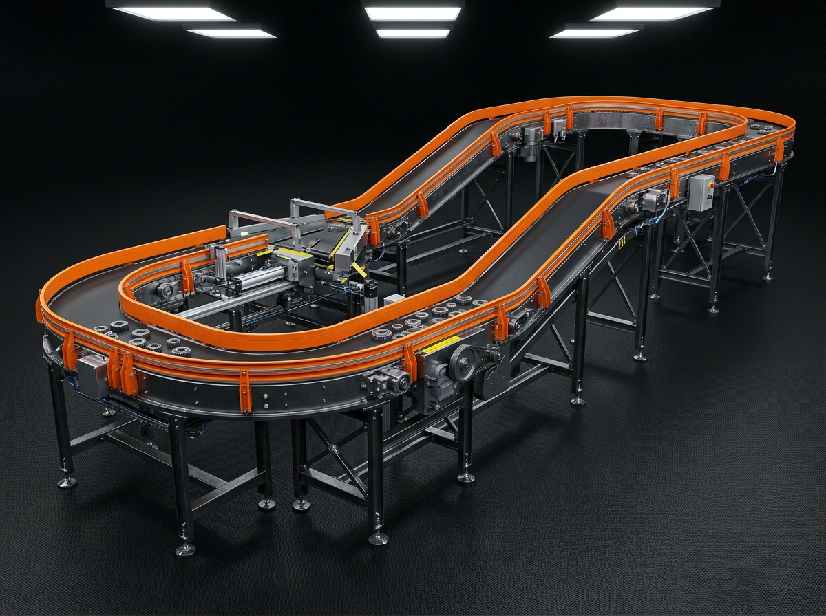
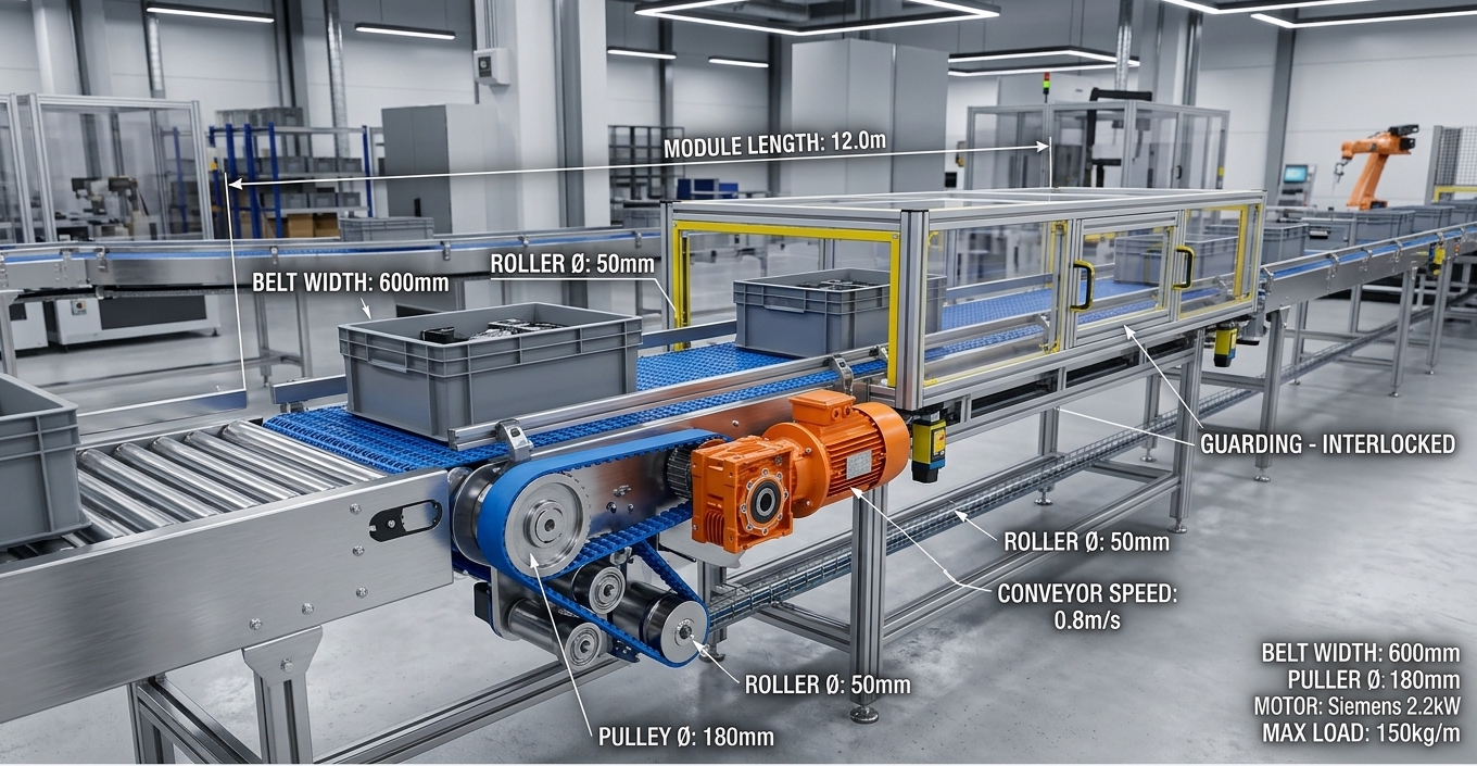
Automated machine conveyor line in manufacturing plant 02
CEMA CALCS .SLDASM MOTOR SIZING

Machine & Conveyor Design

End-to-end mechanical engineering for material handling systems, belt/roller conveyors, transfer mechanisms, and special-purpose machines (SPMs).

  • Belt, roller, modular & chain conveyor designs
  • Drive selection, torque sizing & load calculations
  • Safety guarding & ergonomic frame packages
Detailed Specifications
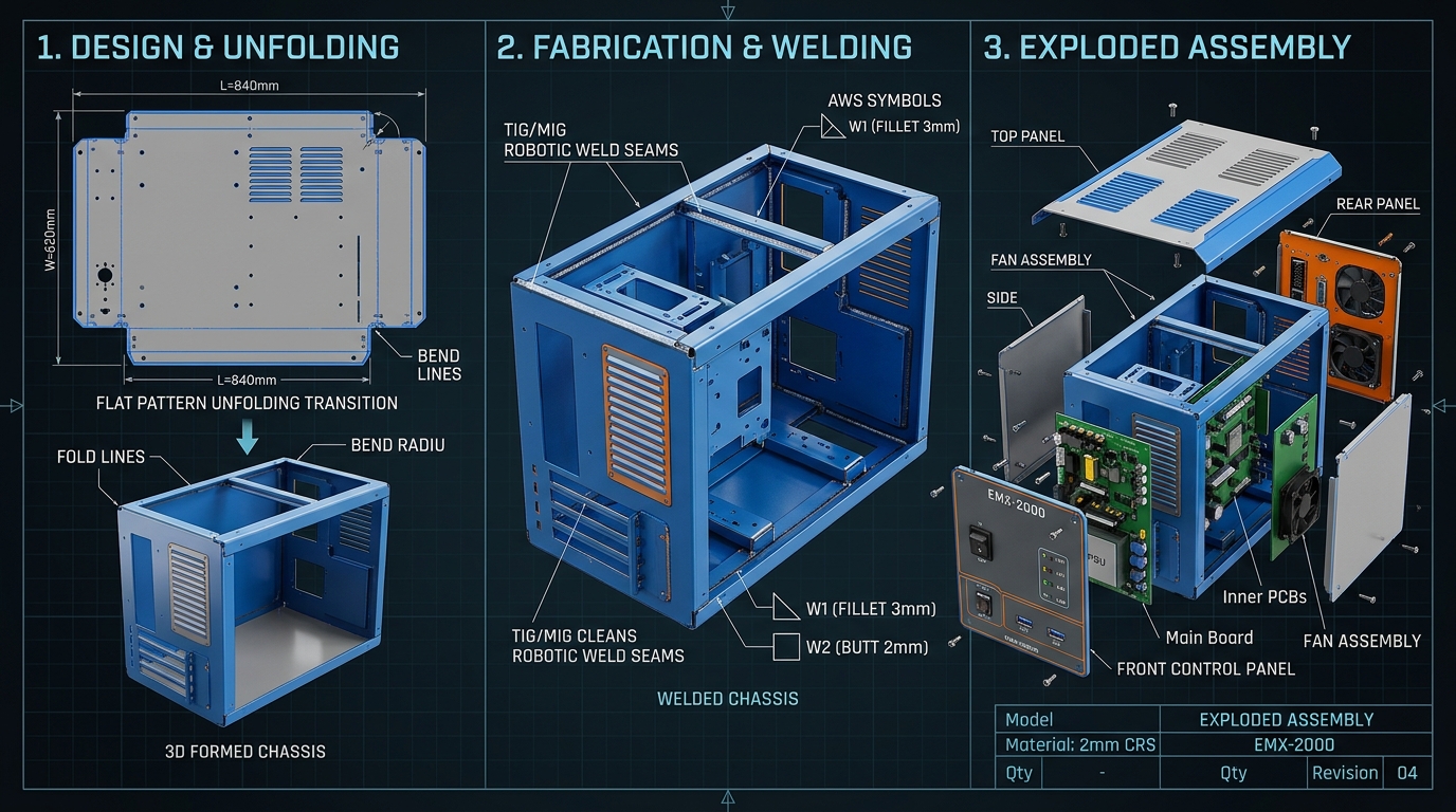
Precision sheet metal laser fabrication and welding 03
1:1 FLAT DXF WELD CUT LIST BEND DEDUCT

Sheet Metal & Weldment Design

Industrial enclosures, machinery guards, architectural louvers, and structural welded chassis with exact bend deductions and cut lists.

  • Precise flat pattern DXF exports with bend lines
  • Weldment cut lists, structural profiles & joint details
  • Gauge optimization for press brakes & laser cutting
Detailed Specifications
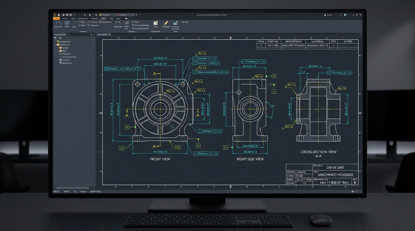
Engineering drafting blueprints and calipers 04
ASME Y14.5 VECTOR PDF AUTOCAD DWG

2D Drafting & Detailing

Shop-floor-ready manufacturing drawings adhering to ASME Y14.5 and ISO standards, complete with GD&T, surface finishes, and organized BOMs.

  • Geometric Dimensioning & Tolerancing (GD&T)
  • Organized Bills of Materials & balloon callouts
  • Legacy 2D drawing to 3D parametric conversions
Detailed Specifications
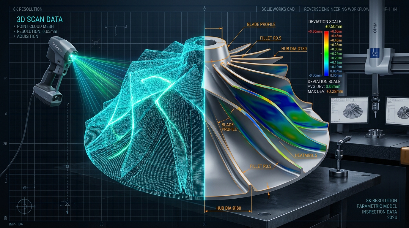
Reverse engineering precision part measurement 05
SCAN-TO-SOLID HEATMAP PDF .SLDPRT NATIVE

3D Scanning & Reverse Engineering

Transforming physical components, scan meshes, or legacy equipment into editable parametric CAD models for aftermarket replacement and benchmarking.

  • Scan-to-CAD parametric solid reconstruction
  • Wear analysis, critical tolerances & material mapping
  • Modernization and manufacturability improvements
Detailed Specifications
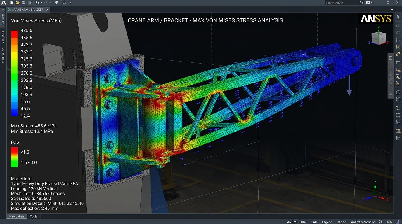
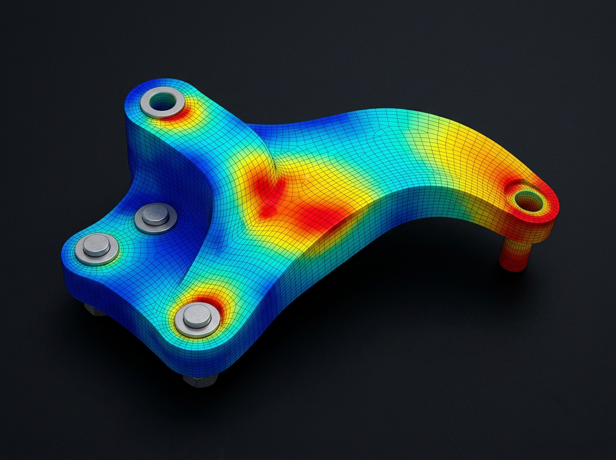
Finite element analysis stress distribution gradient 06
ANSYS .RST FOS REPORT VON MISES

FEA / CFD Analysis

Structural stress, deflection, thermal distribution, and fluid flow simulations to prove design integrity and optimize material before cutting metal.

  • Static structural, modal & fatigue stress assessments
  • Factor-of-safety (FOS) & deflection reports
  • Thermal dissipation & internal fluid flow studies
Detailed Specifications

DriveWorks Design Automation

Transform repeat custom designs into minutes of automated output. We build custom DriveWorks configurators that automatically generate CAD software 3D models, fabrication drawings, cutting files, and accurate configure-price-quote (CPQ) documentation.

Automatic 3D CAD Generation Instant 2D Manufacturing Drawings Automated BOMs & Cost Estimations
Explore DriveWorks Automation
Rules-Based CAD Logic
Eliminate human error and reduce design cycle time by up to 80%.

Software Application Engineering

Full-stack software application engineering for modern enterprises. We design and build scalable web applications, customer portals, cross-platform iOS & Android mobile apps (Flutter / Native), cloud SaaS backends, and custom business automation tools — from concept to App Store launch.

Custom Web Platforms & SaaS Portals iOS & Android Mobile Apps (Flutter) Cloud Backends, REST & GraphQL APIs
Explore Web & Mobile App Services
Web & Mobile Applications
Modern responsive web portals, native mobile apps, and scalable cloud systems.

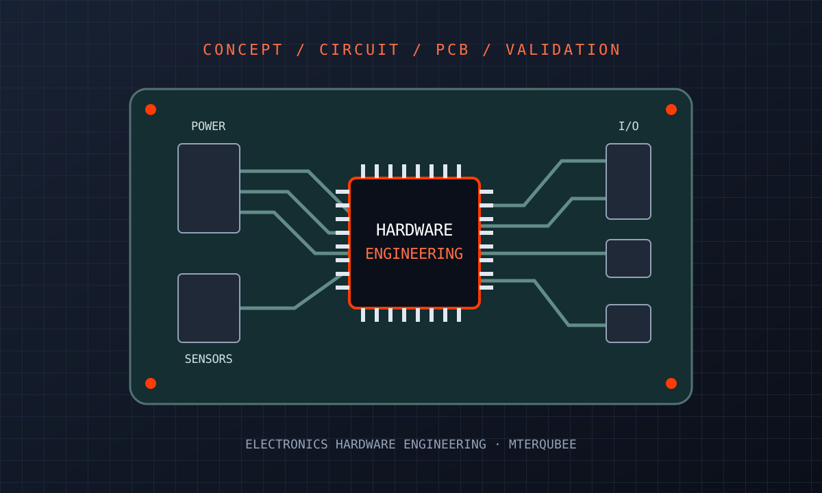
Electronics Hardware Engineering

From board architecture and schematics to PCB layout, prototype verification, and production documentation, develop electronics that fit your product and manufacturing workflow.

Circuit & PCB DevelopmentEmbedded Board IntegrationPrototype & Build Support
Explore Electronics Hardware Services
Electronic circuit board with processor and interface connections
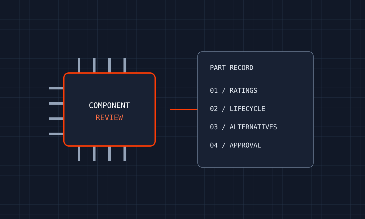
Illustrated electronic component with part record and review checkpoints 10

Component Engineering

Review electronic part data, BOM health, lifecycle risks, and replacement options to support product availability.

  • Part Data Review
  • Selection Support
  • BOM Assessment
Explore Component Engineering
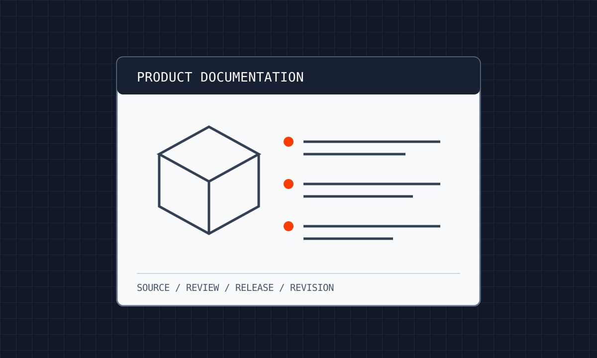
Illustrated technical manual with an assembly diagram and numbered instructions 11

Technical Documentation

Create and maintain product manuals, illustrated parts information, and service guidance tied to the released design.

  • User Guidance
  • Installation Instructions
  • Service Information
Explore Technical Documentation
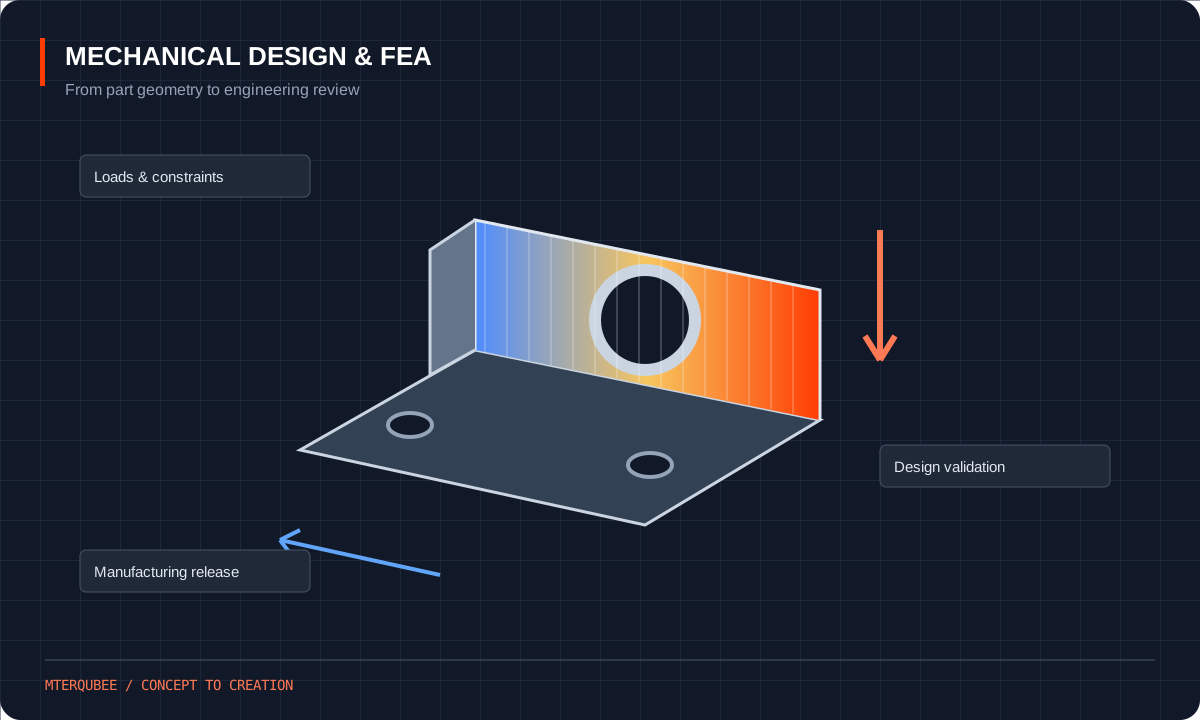
Mechanical Design & FEA workflow illustration12

Mechanical Design & FEA

Develop your product from initial layout to a reviewed engineering package. We bring mechanical design, simulation, and manufacturing documentation together around your requirements.

Explore Mechanical Design & FEA
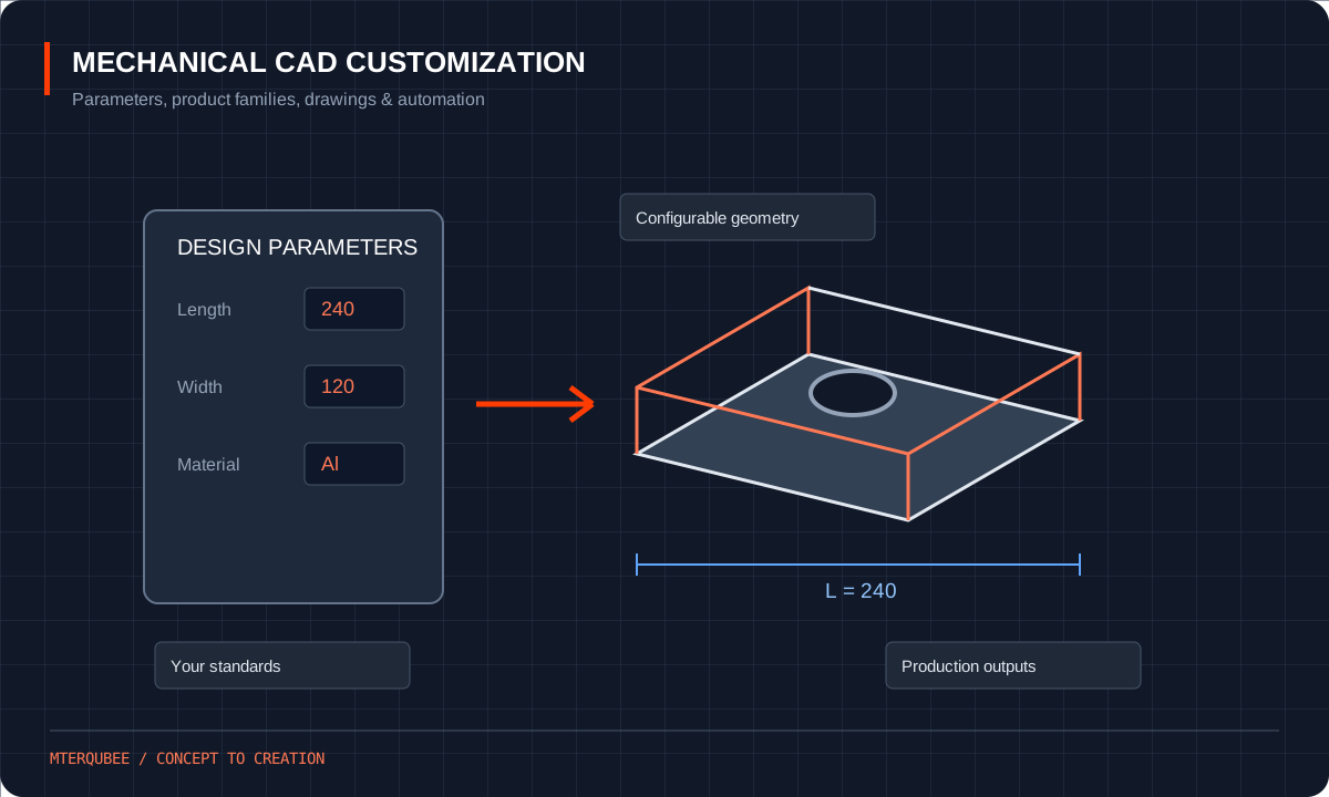
Mechanical CAD Customization workflow illustration13

Mechanical CAD Customization

CAD models and drawings tailored to the way your team designs and builds. Develop custom parts, configurable assemblies, and documentation matched to your engineering standards.

Explore Mechanical CAD Customization
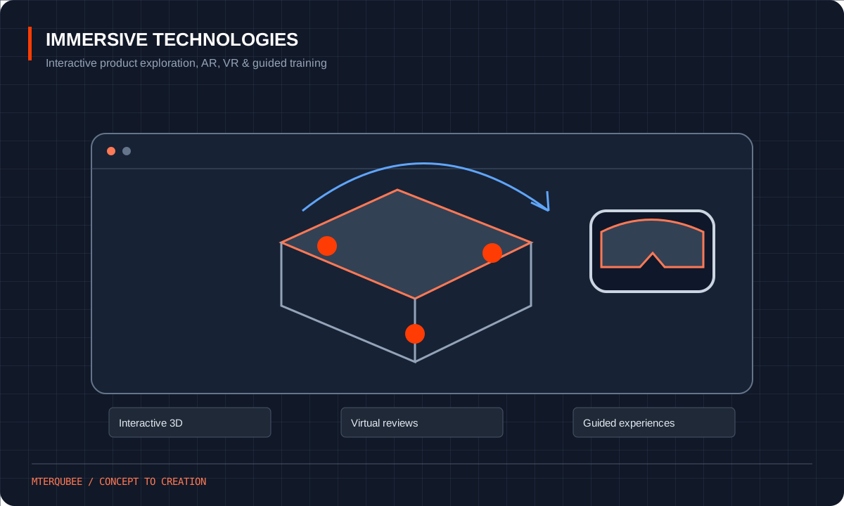
Immersive Technologies workflow illustration14

Immersive Technologies

Help customers and engineering teams understand complex products through interactive 3D, virtual reality, augmented reality, and clear technical visualization.

Explore Immersive Technologies

Engineering Applications & Design Capabilities

Explore engineering workflows from concept development and CAD conversion to simulation, visualization, and automation.

From Hand Sketch to Manufacturing-Ready Product Case Study 01 · Concept to Creation

From Hand Sketch to Manufacturing-Ready Product

A coordinated workflow connecting concept development, 3D CAD assemblies, manufacturing drawings, analysis, and product visualization.

3D CAD Shop Drawings BOM
Explore Case Study
Legacy CAD Conversion for Conveyor Projects Case Study 02 · CAD Conversion

Legacy CAD Conversion for Conveyor Projects

Convert legacy drawings and CAD data into structured, editable models and coordinated conveyor documentation.

2D to 3D CAD Migration Drawing Updates
Explore Case Study
3D Model to CAE / CFD Engineering Analysis Case Study 03 · CAE / CFD Simulation

3D Model to CAE / CFD Engineering Analysis

Evaluate structural and fluid behavior using agreed loads, materials, and boundary conditions to guide design decisions.

FEA CFD Analysis Reports
Explore Case Study
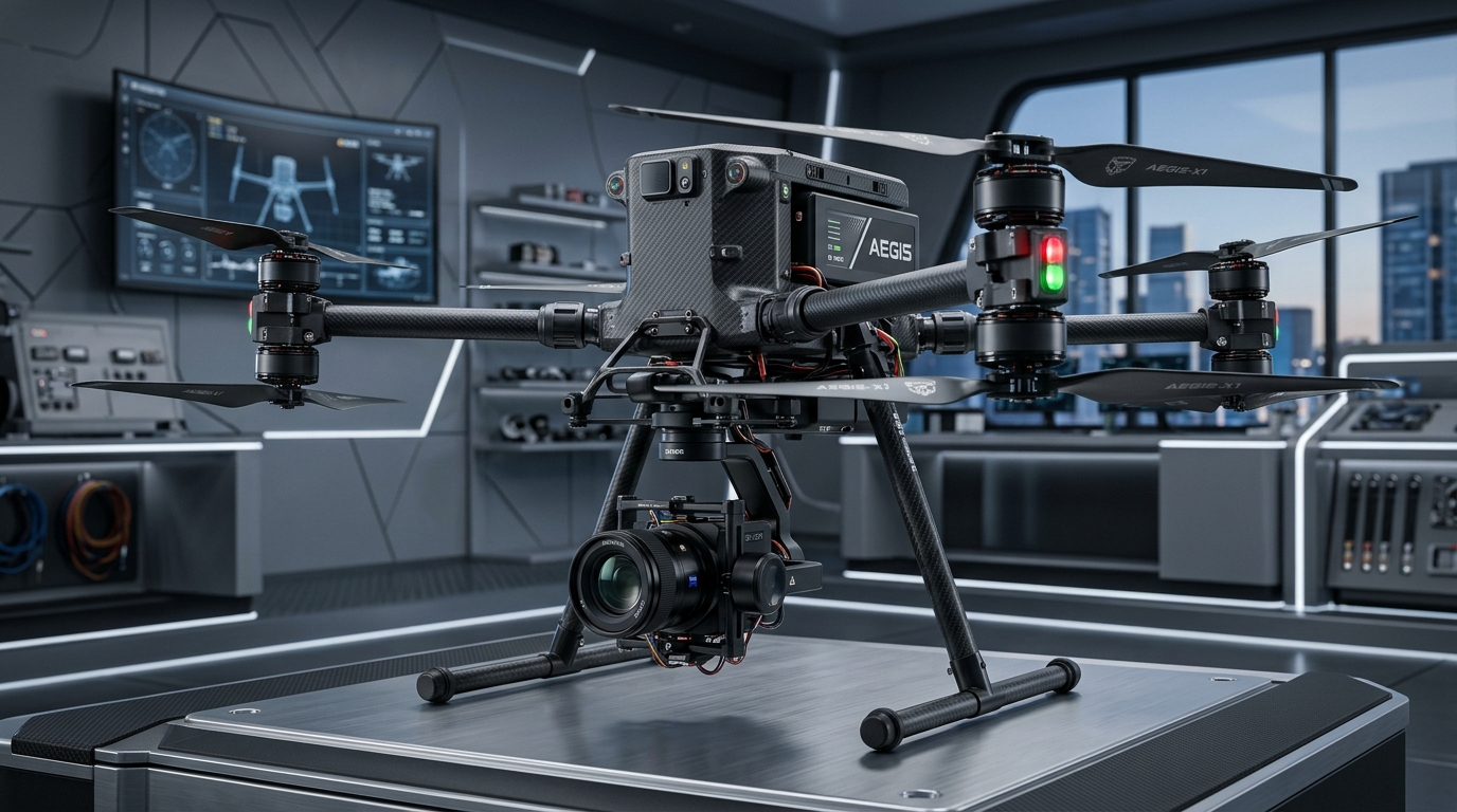
Drone Design, Analysis and Productization Case Study 04 · Drone Engineering

Drone Design, Analysis and Productization

Bring UAV concepts through mechanical design, component integration, engineering analysis, and product documentation.

UAV Design Integration Validation
Explore Case Study
Interior Design Visualization & Walkthrough Case Study 05 · Interior Visualization

Interior Design Visualization & Walkthrough

Translate spatial concepts into detailed 3D environments, photorealistic renders, and animated walkthroughs.

3D Interiors Rendering Walkthroughs
Explore Case Study
Design Automation & CPQ with DriveWorks Case Study 06 · Design Automation

Design Automation & CPQ with DriveWorks

Configure repeat product families with rules-based CAD models, automated drawings, bills of materials, and quotation outputs.

DriveWorks CPQ Automated CAD
Explore Case Study

Our 4-Step Engineering Process

A collaborative, milestone-driven framework ensuring that designs meet mechanical performance, manufacturing limits, and cost targets.

01
PHASE ONE

Define / Explore

// REQUIREMENTS & SCOPE

Investing time at the outset to understand specifications, space constraints, manufacturing budgets, and functional criteria to establish a reliable project roadmap.

02
PHASE TWO

Design / Develop

// 3D CAD MODELING & SIZING

Transforming requirements into 3D CAD models. Conducting preliminary calculations, team design reviews, and engineering evaluations to verify fit and function.

03
PHASE THREE

Deliver / Detail

// 2D BLUEPRINTS & BOMS

Generating full fabrication documentation: manufacturing drawings, GD&T callouts, fastener specs, cut sheets, and assembly BOMs ready for the shop floor.

04
PHASE FOUR

Refine / Finalise

// QA VALIDATION & HANDOFF

Reviewing prototype feedback or pilot production results with your manufacturing team to incorporate refinements, quality checks, and final design freeze.

Industries We Support

Mechanical design, analysis, and manufacturing-ready documentation, tailored to the standards and demands of your sector.

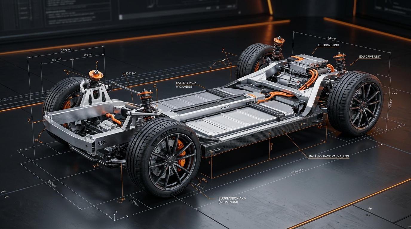
Automotive & EV engineering applications

Automotive & EV

Chassis and suspension components, battery enclosures, brackets, inspection fixtures, and lightweighting studies. We work to IATF 16949 expectations and design for high-volume manufacturing.

Aerospace & Defense engineering applications

Aerospace & Defense

Structural brackets, housings, ground support equipment, and tooling. Our work emphasizes weight optimization, fatigue analysis, traceable documentation, and tight-tolerance GD&T.

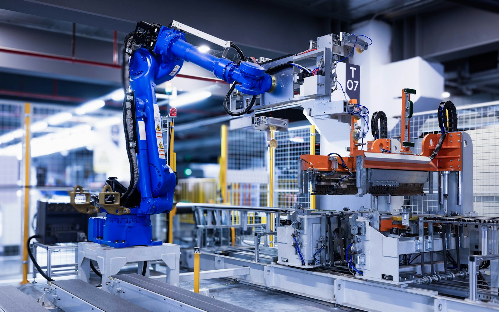
Industrial Machinery & Automation engineering applications

Industrial Machinery & Automation

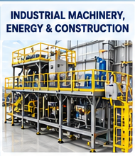
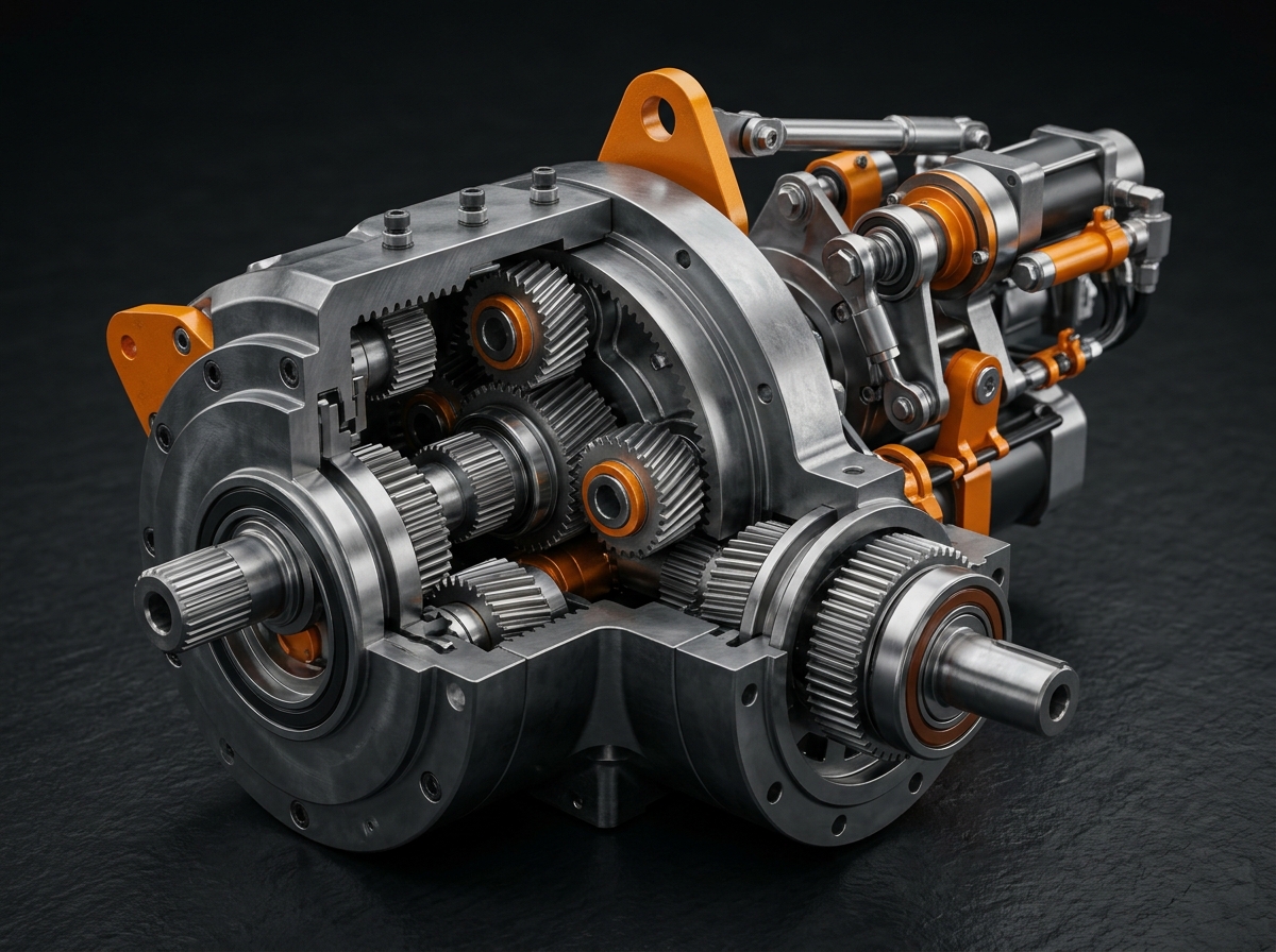
Custom machines, conveyors, robotic cells, gearboxes, and pneumatic or hydraulic assemblies, from concept layout through detailed drawings and BOMs.

Oil, Gas & Energy engineering applications

Oil, Gas & Energy

Pressure vessels, piping supports, skids, heat exchangers, and wind or solar mounting structures, designed to ASME, API, and relevant local codes.

Heavy Equipment & Construction engineering applications

Heavy Equipment & Construction

Frames, booms, attachments, and welded structures, with FEA-backed strength validation and weldment drawings built for fabrication shops.

Medical Devices & Healthcare Equipment engineering applications

Medical Devices & Healthcare Equipment

Enclosures, instrument housings, surgical tool concepts, and lab equipment, with attention to material selection, cleanability, and documentation for regulated environments.

Consumer Products & Electronics engineering applications

Consumer Products & Electronics

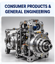
Product enclosures, thermal management, injection-molded parts, and tooling-ready designs with draft, wall thickness, and assembly considerations built in.

HVAC, Process & Packaging engineering applications

HVAC, Process & Packaging

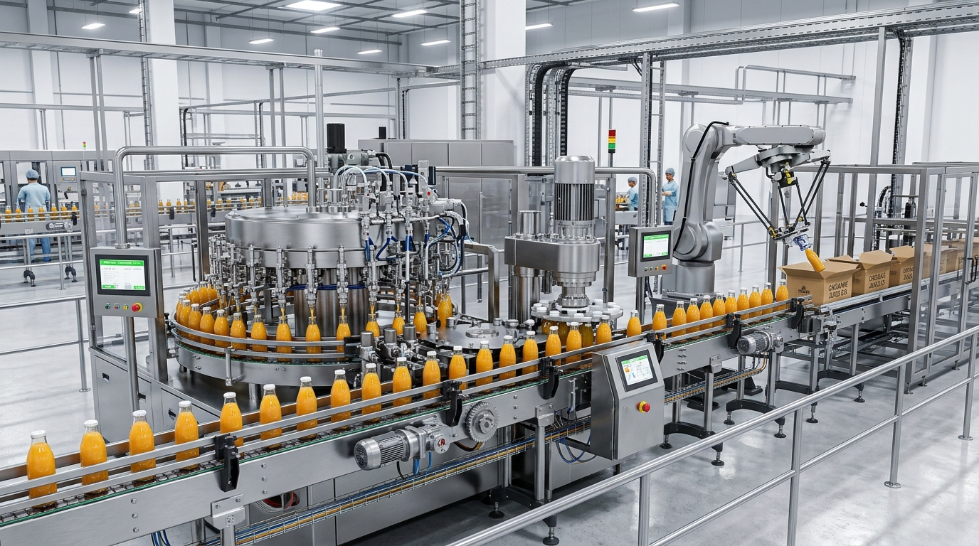
Ducting, heat exchangers, sheet-metal enclosures, filling and packaging machines, and food-grade stainless equipment.

Engineered for Technical Credibility & Commercial Value

Every design we deliver is built to pass an engineer’s review and a CFO’s scrutiny.

Technical Credibility

Validated, not assumed.

Critical parts are checked with FEA, fatigue, thermal, and motion studies before release, and key results are confirmed through prototype testing.

Standards-compliant documentation.

Drawings follow ASME Y14.5 or ISO GPS conventions, with full GD&T, tolerance stack-ups, material specs, and clean BOMs that any machine shop or supplier can quote from.

Traceable and controlled.

Revision control, design reviews, and change logs keep every file auditable from first concept to final release.

Engineers who have built it.

Our designers understand machining, casting, sheet metal, welding, and molding, so the design on screen is the design that gets made.

Commercial Value

Lower unit cost.

Design for manufacturing and assembly (DFM/DFA) reduces machined faces, part count, and fastener variety.

Faster time to market.

Parametric models and reusable design libraries shorten iteration cycles and cut revision rounds.

Less risk, fewer reworks.

Early simulation and tolerance analysis catch problems at the CAD stage, where fixes are cheapest.

Production-ready deliverables.

Native CAD, STEP files, 2D drawings, BOMs, and assembly instructions are delivered in a package ready for your supplier or production team.

Industry-Grade Engineering Software & Tools

We work with the same professional-grade platforms your manufacturing and engineering teams rely on every day.

3D CAD & Product Design SolidWorks, CATIA, Autodesk Inventor, Fusion 360, Siemens NX, PTC Creo Parametric part modeling, large assemblies, surfacing, sheet metal, weldments, and motion studies.
CAD
2D Drafting & Documentation AutoCAD, SolidWorks Drawings, DraftSight Manufacturing drawings with GD&T, tolerance callouts, BOMs, and ISO/ASME-compliant standards.
2D
Simulation & Analysis (CAE) ANSYS, SolidWorks Simulation, Abaqus, Fusion 360 Simulation Static and fatigue FEA, thermal analysis, modal and vibration studies, and CFD for flow and heat transfer.
CAE
CAM & Manufacturing Preparation Mastercam, Fusion 360 CAM, SolidCAM Toolpath generation for CNC milling and turning, plus design-for-manufacturing checks before release.
CAM
Rendering & Visualization KeyShot, SolidWorks Visualize, Blender Photorealistic renders, exploded views, and assembly animations for client presentations and marketing.
3D
Data, PLM & Collaboration SolidWorks PDM, Teamcenter, Windchill, Excel, MATLAB Version control, revision management, engineering calculations, and design data analysis.
PLM

What Our Global Clients Say

Real feedback from manufacturers and engineering teams across 10+ countries who rely on Mterqubee for precision design work.

"Mterqubee delivered our complete conveyor system CAD package — including all weldments, BOMs, and GD&T drawings — in under two weeks. The quality was exceptional and required zero revision rounds."
MH
Mark H. Director of Engineering · Material Handling OEM, USA
"We needed FEA validation on a critical hydraulic cylinder design before production. Mterqubee's simulation report clearly identified the stress concentrations and provided a corrected geometry — saving us thousands."
AK
Arjun K. Senior Engineer · Hydraulics Manufacturer, India

Engineering Partners Across 10+ Countries

From small product startups to large-scale OEMs, Mterqubee supports engineering teams around the world with precision CAD, simulation, and automation services — all managed remotely from our Hyderabad design center.

USA & Canada
United Kingdom
Australia
Germany
UAE & Gulf
Singapore & SEA
0
+ yrs
Engineering Experience
0
+
Projects Completed
0
+
Countries Served
0
%
Business Growth YoY

Mechanical Design Engineering Training

Build practical CAD, CAE, and automation skills with industry-oriented training, freelance project support, and career development guidance.

Ready to Discuss Your Engineering Requirements?

Send us your project scope, CAD sketches, or RFP specifications. Our Hyderabad engineering team will review your requirements and provide a clear technical proposal.